KOA Speer Fundamentals of LTCC Substrates
What is LTCC?
LTCC stands for Low Temperature Co-fired Ceramics. It is a ceramic multilayer substrate. This technology permits to use low resistive material as conductor patterns due to the lower temperature needed during firing process compared to general ceramic firing process. This is achieved by adding glass to alumina.
Combining alumina and glass-based materials enables the firing at 1000 ºC or lower, and silver (Ag: melting point = 960 ℃), which is a low-resistance conductor, can be used as a wiring conductor.
This make it possible to fabricate a multilayer substrate with excellent electrical characteristics with less loss due to low conductor resistance, which is advantageous for high frequency performance.

Since the base material is ceramic, it has excellent heat and moisture resistance and no outgassing. In addition, since the thermal expansion coefficient is relatively close to that of silicon, it is an advantageous substrate for bare chip mounting. Moreover, the height can be reduced by mounting in the cavity.
Because of these features, they are widely used in high-frequency modules, substrates for semiconductor packages, and substrates for applications that require environmental resistance.
Structure

Multilayer Ceramics & Cavity Packages
Enable Complex Module Creation
- Optimal for Bare Chip Modules
- Highly controlled dimensions and flatness
- Low thermal expansion enhances use of ICs
- High-Frequency Performance
- Ceramics with low dielectric constant and loss
- Low ohm silver conductor
- Miniaturization & Integration
- Multilayer and multi-cavity structures
- Surface and buried printed resistors
- Environmental Reliability
- High heat and moisture resistance (zero water absorption)
- No outgassing - Dust-free - Impermeable
Description of each series
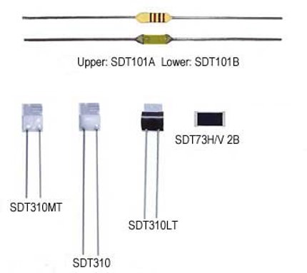
SDT101 series
SDT101 series is less expensive than platinum thin film thermal sensors that comply with IEC standards. KOA has been delivering this product since 1982. The approximate expression of temperature resistance characteristics is available to be used for circuit calculation at the time of design.
Since the element section does not have directionality due to its cylindrical shape, they perform excellent as wind-velocity sensors or as flow sensors utilizing self-heating.
The SDT101 series are mainly used for the temperature compensation of load cells, wind-velocity sensors utilizing self-heating, the cold junction compensation of thermo-couples, the flow measurement of electronic fuel injector of automotive, and the compensation of various temperature sensors.
SDT310 Series
SDT310 series has a small element, ability to have 1kΩ and excellent response and linearity. SDT 310 LT model can be soldered easier among this series. The SDT310MT achieves CLASS B for temperature measurements at 650 ºC, where a thermocouple or expensive wire wound type had to be used.
They are mainly used for high-precision temperature measurement, cold junction temperature compensation for thermo-couples, temperature compensation for control boards, and temperature management for electronic devices.
SDT73H / SDT73V series
SDT73H and SDT73V series are surface mount type thin film platinum thermal sensors with T.C.R. conforming to JIS/IEC standards. Qualified data for the automotive standard test, AEC-Q200, is available for SDT73V.
ST series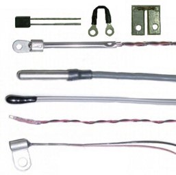 ST series consists of customized products, in which a product of SDT series is sealed in a protective tube, mounted on a board or its lead wires are extended.
Going forward, KOA will continue to expand the lineup of products that are even more compact, have higher precision, can handle high temperatures, and have a wide range of measuring temperatures so that we can flexibly meet customer needs.
History
A platinum wire wound type thermal sensor that is one of the thermal sensors, also called Pt100 and conforming to JIS and IEC, has been widely used for a long time. Although this product is very expensive due to the use of platinum wire, it is resistant to the environment, stable for a long time, and has characteristics according to the internationally determined calculation formula and the conversion table of temperature-resistance value.
The platinum wire wound type is originally more expensive than other resistance temperature sensors. To have the resistance value larger than 100 ohm, the size becomes larger and the price becomes higher. Therefore, the platinum wire wound types have been considered as high-priced thermal sensors.
Since 1982, KOA have been commercializing and selling a platinum thin-film thermal sensors with high resistance value and affordable price. This product has an excellent temperature accuracy and temperature characteristics achieved by KOA's original technology, and has been used in the field of measurement equipment as a product with high-precision and high-stability.
Since the commercialization of thin-film thermal sensors in accordance with JIS standards in 1997, the reliability of thin-film types has been widely recognized, and the demand has increased.
Recent increase in demand is due to the customers' need for high-precision and customized shape to enhance the added value of their product. In addition, stricter process control has become required in food processing, which has led to an increase in demand.
The factors that platinum thin-film thermal sensors have been accepted in the market; roughly the same performance as wire wound types, low price, high resistance value(1kΩ) in small size achieved by thin-film, and fewer errors caused by the resistance of lead wire achieved by the large resistance change. Above factors made the designing of circuit in set easy.
As a recent trend, the demand for new custom-shaped platinum thin-film thermal sensors is increasing.
Example:
・Temperature sensors mounted on glass epoxy board
・Molded type
This trend is expected to increase as equipment manufacturers shift to higher value-added products.
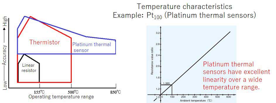
Temperature characteristics of a resistance thermal sensor
The types of thermal sensors whose resistance changes with temperature are roughly classified into thermistors, linear resistors, and platinum resistance thermal sensors. The temperature characteristics of each are shown below.
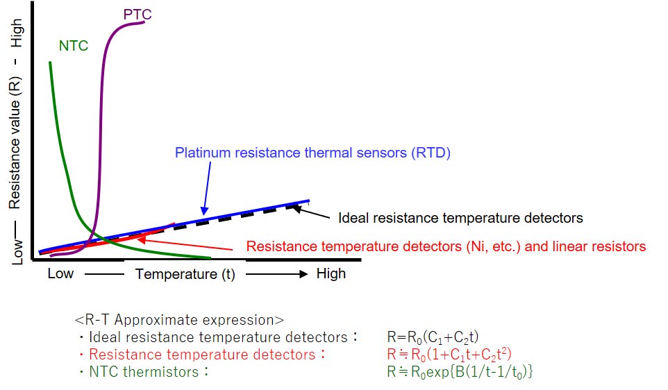
Characteristics of a thermal sensor
Resistance temperature detector(RTD)
Resistance temperature detectors have the characteristic that the resistance value increases linearly with increasing temperature. Platinum resistance thermometers are particularly excellent in linearity and long-term stability. They can be used over a wide temperature range and their resistance tolerance and T.C.R tolerance are highly accurate. The platinum resistance thermal sensors Pt100 (100Ω at 0 °C) is used as a standard in JIS standard, and there are other variations within the range of 10Ω to 1kΩ.
- Resistance value change of the resistance temperature detectors is almost linear to the temperature
- Use metals such as platinum, nickel and copper
- Platinum has excellent stability and linearity and covers a wide temperature range.
Linear Resistors
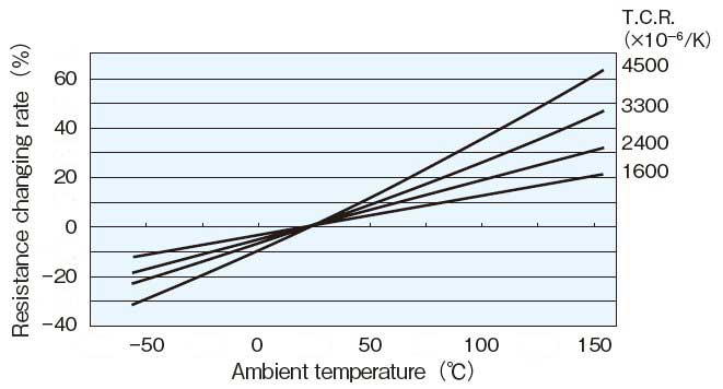
Linear resistors have a characteristic that resistance increases linearly with increasing temperature, but they are not as accurate as platinum resistance thermal sensors. It has long been used for temperature compensation of motor windings, and in recent years it has also been used for temperature compensation of high-frequency circuits and displays.
- Uses a point where the resistance increases almost linearly with temperature.
- Uses the alloy of Nickel and Palladium.
- Various resistance values and T.C.R. can be selected.
Thermistor (PTC/NTC)
Thermistors are elements whose resistance varies with temperature. There are two types of thermistors: PTC type (positive characteristic), in which the resistance increases as the temperature increases, and NTC type (negative characteristic), in which the resistance decreases as the temperature increases. The resistance value of PTC types increases rapidly at a certain temperature. These characteristics are used to protect semiconductors from overcurrent during thermal runaway.
The resistance value of NTC types decreases exponentially with increasing temperature, and is high at room temperature, and the amount of its change with temperature is large. NTC types are generally used in protection circuits for secondary batteries of smartphones and others and are used the most among temperature sensors. Since NTC thermistors have a relatively large aging variation, design considerations are required for equipment that requires long-term reliability. Since the term thermistor generally refers to NTC type, NTC thermistors will be referred to as thermistors hereafter.
Temperature characteristics of NTC thermistors
The resistance value R at t°Cis approximately given below
R = Ro•exp{B(1/T-1/To)}
R : Resistance value at temperature T(K) [T(K)=t(°C)+273.15]
Ro : Resistance value at temperature To (K)
B : This is called B constant and its unit is (K)
In the thermistor catalog, the resistance value at 25°C is described as Ro
- Utilizing resistance temperature characteristics of semiconductors
- Is small and highly sensitive
- Has nonlinear resistance temperature change characteristics
- Large aging variation
Operating temperature range and accuracy
The operating temperature range and accuracy differ depending on the type of thermal sensor.
Comparison between resistance temperature detector and linear resistors
Resistance temperature detector
Features for temperature mesurement
- High linearity accuracy
ex: Tolerance for temperature of Pt100- Class A: ± (0.15+0.002 |t| )°C
- Class B: ± (0.3+0.005 |t| )°C
- Pt100 has been standardized
- Few options of resistance and T.C.R.
- To be used under a condition with low self-heating
| Temp.(°C) | 0 | -1 | -2 | -3 | -4 | -5 | -6 | -7 | -8 | -9 |
|---|---|---|---|---|---|---|---|---|---|---|
| -50 | 82.04 | 81.67 | 81.31 | 80.94 | 80.58 | 80.22 | ||||
| -40 | 85.66 | 85.29 | 84.93 | 84.57 | 84.21 | 83.85 | 83.49 | 83.12 | 82.76 | 82.40 |
| -30 | 89.26 | 88.90 | 88.54 | 88.18 | 87.82 | 87.46 | 87.10 | 86.74 | 86.38 | 86.02 |
| -20 | 92.85 | 92.49 | 92.13 | 91.78 | 91.42 | 91.06 | 90.70 | 90.34 | 89.98 | 89.62 |
| -10 | 96.43 | 96.07 | 95.72 | 95.36 | 95.00 | 94.64 | 94.29 | 93.93 | 93.57 | 93.21 |
| 0 | 100.00 | 99.64 | 99.29 | 98.93 | 98.57 | 98.22 | 97.86 | 97.50 | 97.15 | 96.79 |
Linear resistors
Features for temperature measurement
- Low linearity accuracy
- Wide variety of resistance values
- Many variety of T.C.R.
- High power rating
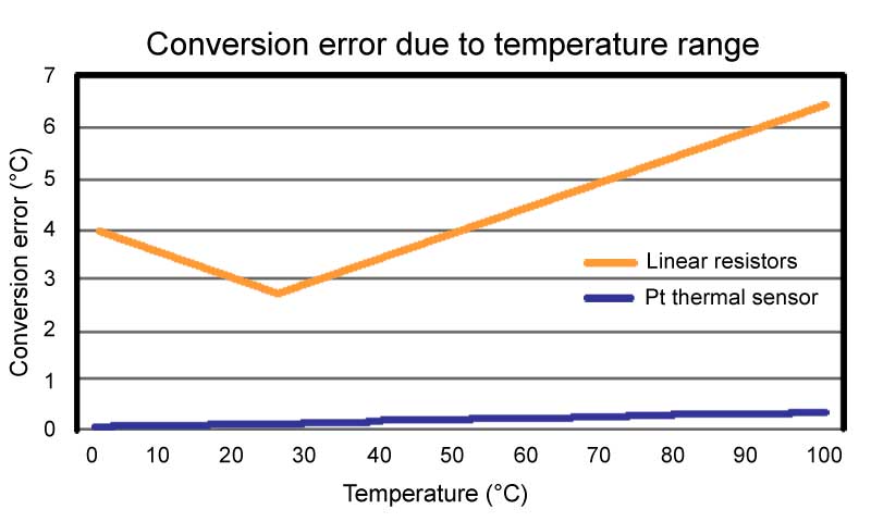
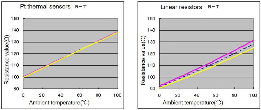
Temperature conversion error
The temperature characteristics of the linear resistor being different between Cold T.C.R. and Hot T.C.R. divided at 25 °C. The platinum resistance thermometers have stable T.C.R. within the operating temperature range.
Variation in temperature characteristics
Thermistor linearization
The resistance changes of thermistors vary widely when the temperature ranges to some extent. To narrow the variation, the thermistor is linearized. Linearization includes a voltage mode in which a positive output voltage is obtained with respect to a temperature change, and a current mode in which a negative output voltage is obtained.
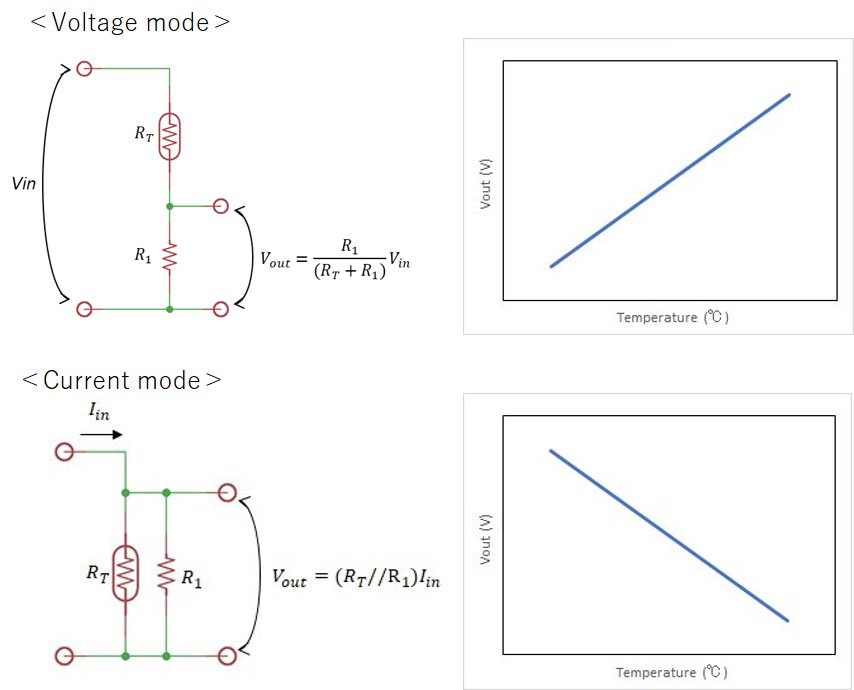
How to determine the resistance value of R1
R1 can be obtained from the output voltage at the operating temperature for both the voltage mode and the current mode. Following demonstration will be using the voltage mode (series connection).
The conditions are as follows.
・Input Voltage:Vin
・Series resistance value:R1
・Resistance value of thermistor:RT
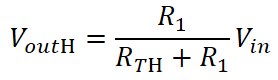
Output voltage Vout is calculated from the following formula
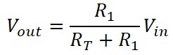
Calculate R1 value suitable for the operating temperature range.
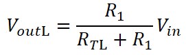
The resistance and output voltage of the thermistor at the operating temperature of lower limit, intermediate, and upper limit are as follows.
・Lower limit temperature RTL, VoutL
・Intermediate temperature RTM, VoutM
・Upper limit temperature RTH, VoutH
Calculate output voltage at each temperature.
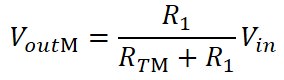
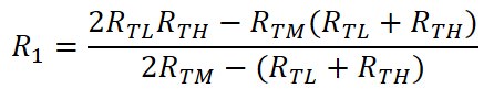
Since VoutM-VoutL = VoutH-VoutM is suitable for linearization, we can obtain the formula 2 VoutM = VoutH-VoutL. Substituting the equation for the output voltage at each temperature into this equation and obtain R1 value from the following equation.
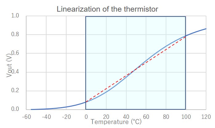
Example of linearization on NTC thermistor “NT732ATD223”
Conditions
・Vin 1V
・Operating temperature range 0~100℃
・B constant of thermistor 3800
・Resistance value of thermistor R0 at 25℃ 22kΩ
From the thermistor characteristics for resistance and temperature
R=R0 exp {B(1/T – 1/T0)} and T(K)=273℃+t℃, we can obtain thermistor resistance value at 0℃, 50℃, and 100℃ is calculated as follows;
RT0=70.637kΩ, RT50=8.207kΩ, RT100=1.698kΩ
From these values, R1 is calculated to be 6.52 kΩ.
Plotting the Vout graph from this R1 value results in:
Summary
Each thermal sensor has various characteristics. For temperature control and temperature measurement, it is necessary to understand the characteristics of each and use them properly.
| Resistance temperature detector | Linear resistors | NTC thermistors | ||
|---|---|---|---|---|
| Pt(Platinum) | Other metals | |||
| Measurement accuracy | Excellent | Good | Poor | Fair |
| Stability | Excellent | Fair | Fair | Fair |
| Resolution (Change of Resistance value/°C) |
Fair | Fair | Fair | Excellent |
| Measuring temperature range | Good | Fair | Fair | Fair |
| Temperature measuring correction circuit | Unnecessary | Unnecessary | - | Necessary |
| Compatibility | Excellent | Good | Fair | Fair |
| Selectivity (Resistance value & T.C.R.) |
Poor | Fair | Excellent | Excellent |
| Application | Temperature measurement | Temperature measurement | Temperature compensation | Circuit protection |